 KERRSCOPE
one geodesic per pixel
Gravitational lensing here is not a screen-space effect. It is an integration.
A real-time Kerr black hole ray tracer. For every pixel on the screen the shader integrates Hamilton's equations backwards through curved spacetime until the photon lands on the disk, on an orbiting body, on the sky, or inside the hole. The shadow and the photon ring are not drawn. They fall out of the integration.
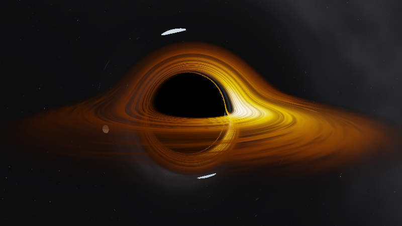
a/M = 0.85, disk outer edge 20 M, camera at
26 M. Rendered by the program, not illustrated. The bright side is
the approaching side: specific intensity scales as g³.
What happens to one pixel
Five steps, about 163 of them per ray
Units are geometrised, G = c = 1, so every length below is in
units of GM/c². The order matters — this is the sequence the
shader runs, per pixel, per frame.
Convert the camera position from pseudo-Cartesian coordinates to Boyer-Lindquist
(r, θ, φ).Build the photon four-momentum in the local orthonormal frame of a zero angular momentum observer, normalised to unit local energy.
Lower indices with the covariant Kerr metric to get the conserved
E = −p_tandL = p_φ.Integrate Hamilton's equations with RK4, using analytic derivatives of the inverse metric.
tandφare cyclic, so only five quantities are carried.Accumulate emission at every equatorial crossing between the ISCO and the disk's outer edge; sample a procedural sky if the photon escapes to
r = 1000 M.
dxⁱ/dλ =  ∂H/∂pᵢ        H = ½ g^{μν} p_μ p_ν   ( = 0 for a photon )
dpᵢ/dλ = −∂H/∂xⁱ
The emitting gas orbits prograde at Ω = √M / (r^{3/2} + a√M). Because
the photon was normalised to unit energy in the camera frame, the whole
redshift factor collapses to g = 1 / [ u^t (E − Ω L) ] — gravitational
redshift, transverse and longitudinal Doppler and frame dragging in one
number.
Measurement
The integrator is held to analytic results, not to taste
This is a physics calculation that happens to draw pictures, so it is checked the way a calculation is checked. A double-precision harness runs the same equations as the shader and compares them against values that are known in closed form. Every number below is asserted in CI on every push.
| Spin a/M | Numeric b | Analytic b | Rel. error | p99 steps |
|---|---|---|---|---|
| 0.00 | 5.196153 | 5.196152 | 8.2e−08 | 126 |
| 0.50 | 4.096267 | 4.096267 | 1.4e−07 | 131 |
| 0.85 | 3.054337 | 3.054336 | 1.6e−07 | 149 |
| 0.95 | 2.582213 | 2.582212 | 2.0e−07 | 163 |
b_crit is the strongest single check in the project, because it
is the angular radius of the shadow. It only comes out right if the
metric, the ZAMO tetrad, the constants of motion and the integrator are
all correct at the same time. The row for a/M = 0.85 is the
measurement labelled in Fig. 1.
| Null condition H = 0 along a ray, a/M = 0.9 | max |H| = 2e−06 |
| Weak-field deflection vs 4M/b + 15πM²/4b² | 1.0e−04 at b = 320 M, falling as 1/b² |
| Frame dragging, radially aimed photon | +2.15986 rad at a/M = 0.9; exactly 0 at a = 0 |
| Fragment-shader port vs the original compute shader | 0 of 360000 pixels differ |
Numbers are not the whole story, and the project says so. Cross-compiling
the shader to a CPU renderer and looking at the output caught two bugs
every numerical test had passed: a dark seam along the projected spin
axis from the sin θ → 0 coordinate singularity, and stars visible
inside the shadow, where RK4 stages stepped to r < r₊, Δ
changed sign and photons were ejected back out.
Spin
Frame dragging is visible, and it is in the photon paths
Frame dragging enters through the g^{tφ} terms of the metric, so it
bends the light itself rather than tinting what is behind it. Switch the
spin and watch the shadow go off-centre and flatten on the approaching
side.
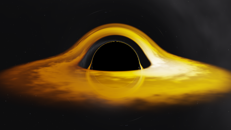
a/M = 0.85. The orbiting bodies are on in this frame and off in the a = 0 one, so ignore the white arcs and watch the shadow.
Constraint
It runs on a laptop from 2012
The geodesic integration is in a fragment shader rather than a compute shader. Nothing here needs compute support, storage buffers or any extension: OpenGL 3.3 core is the floor, and it is a deliberate one.
Cost is roughly pixels × steps. The renderer traces at a fraction of the window resolution and then converges: each frame jitters the ray on a Halton sequence and averages into a float buffer as an exact running mean, so a still camera reaches a clean antialiased frame in about a second. That suits slow hardware far better than blurring would — the photon ring is a couple of pixels wide, and blur destroys exactly the feature you came to look at.
| Render scale | Traced pixels | Per frame |
|---|---|---|
| 0.15 | 192 × 108 | ~0.9 GFLOP |
| 0.25 (default) | 320 × 180 | ~2.4 GFLOP |
| 0.35 | 448 × 251 | ~4.6 GFLOP |
| 0.50 | 640 × 360 | ~9.4 GFLOP |
What it does not do
The limits, stated rather than discovered
- Spin is capped at a/M = 0.95
-
Near extremal, the outer horizon, the inner horizon and the prograde
photon orbit crowd into a shell a few hundredths of
Mthick. Boyer-Lindquist ray tracing in 32-bit floats stops being trustworthy there: photons leak back out and speckle the shadow, measured at 3.6% of shadow pixels ata/M = 0.998against 0% at 0.85. Fixing it properly needs horizon-penetrating coordinates. - About 0.4% of pixels exhaust the step budget
- They render black. Raising the cap from 320 to 700 changes nothing, so those rays are genuinely trapped near the photon shell rather than merely slow. The visible effect is a thin dark arc exactly where the photon ring is brightest — cosmetic, but it is there.
- The disk is a zero-thickness sheet
- A Novikov-Thorne-like radial profile with procedural turbulence. It is not a radiative-transfer solution, and the turbulence is noise rather than magnetohydrodynamics. Light travel time is not accounted for in its rotation.
- The disk colour is an artistic choice
-
diskTemperaturedefaults to 2000 K, and the documentation says plainly that this is a choice. A physically realistic accretion flow at 10⁴–10⁷ K renders as a white smear with no visible colour structure, because the normalised Planckian locus is almost colourless above about 5000 K. The physics is identical either way; only the colour lookup changes.
Get it
Download a build, or compile it in two commands
Releases carry a Linux binary and a Windows .exe, each with the
shaders alongside. Unpack and run — there is nothing to install.
# needs a C++17 compiler, CMake 3.16+
# and an OpenGL 3.3 driver
cmake -S . -B build -DCMAKE_BUILD_TYPE=Release
cmake --build build -j
./build/kerr
GLFW and GLM are taken from the system if they are there and fetched if they are not. There is no third dependency: the GL loader is 44 entry points, vendored, and the PNG writer emits DEFLATE stored blocks rather than linking zlib.